

A structural engineer is working on a twelve-storey commercial tower. The physical Revit model is current — the architect's latest revision was incorporated last week. The analytical model in Robot Structural Analysis is from two months ago. Between the two models, there are seven discrepancies: a beam that has changed depth, a column that has moved, a slab that has been thickened, a wall that has been added, and three connections that have been revised.
This is not an unusual situation. It is the normal state of a design team under programme pressure. And it is the origin of analytical drift.
What Analytical Drift Actually Is
Analytical drift is the progressive desynchronisation between the physical model held in Revit and the analytical model exported to ETABS or Robot Structural Analysis. The physical model is the source of truth — it represents what is being built: column sizes, beam depths, slab thicknesses, wall positions, and foundation layouts. The analytical model is derived from it. Every analytical beam is a parametric representation of a physical beam; every analytical column is a centreline abstraction of a physical column.
When the architect updates the physical model — moving a wall, increasing a beam depth, adding a new opening — the structural engineer must manually update the analytical model to match. In traditional practice, this is done by opening the analytical model settings and manually repositioning every affected analytical element. The process is labour-intensive, error-prone, and cumulative. After multiple rounds of design development, the two models begin to diverge.
A beam that appears in the physical model at Level 3 has been moved by the architect but not updated in the analytical model. A column that has been resized has retained its old analytical section properties. A slab that has been thickened has not been updated in the rigid diaphragm definition. The physical model says one thing. The analytical model says another.
Why the Consequence Is Severe
The consequence is not a documentation problem. The consequence is that the structural calculations are mathematically void under Eurocode.
Specifically, EN 1993-1-1 (Design of steel structures) and EN 1992-1-1 (Design of concrete structures) require that the structural calculation be based on a model that accurately represents the as-designed structure. An analytical model that is out of sync with the physical model does not represent the as-designed structure. The calculation may be numerically elegant. It may produce results that look reasonable. But if the analytical model does not accurately represent the physical structure, the calculation is structurally meaningless.
A disconnected node in Robot Structural Analysis produces a frame that appears to stand but is structurally impossible. An orphaned analytical element may silently carry zero load — or have been removed from the structural system without the engineer's knowledge. An analytical beam that is 150mm shallower than the physical beam it is supposed to represent will have a different moment capacity, a different deflection, and a different connection design. None of those differences will be visible unless someone compares the two models.
The engineer may not notice until the model is reviewed, or until the connection design is found to be incompatible with the analysis results. At that point, the programme is at risk, the fees are at risk, and the structural integrity of the building is a question that should not need to be asked.
What Automated Physical-to-Analytical Mapping Changes
The automated physical-to-analytical model mapping methodology addresses analytical drift at its source. When the physical model is updated, the alignment rules defined in the Boundary Condition Specification are re-executed across all elements. The mapping is deterministic: the same physical model with the same alignment rules produces the same analytical model.
This is not a vague aspiration. It is a mathematically verifiable statement. The mapping run is reproducible. The same input — the same physical model geometry, the same alignment rules — produces the same output — the same analytical model — every time. The Structural Engineer reviews the Error Log, resolves orphaned nodes, and confirms the nodal connectivity before export. The final model is their professional output: guaranteed-synchronised, verifiable, and structurally sound.
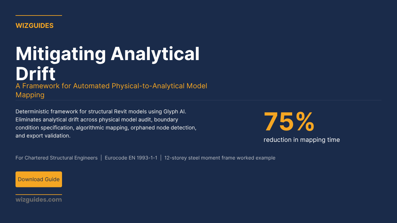
The twelve-storey worked example in the WIZGUIDES methodology demonstrates the impact in practice: Dr. Priya Nair, CEng MICE, reduced mapping time from eight working days to two working days on a twelve-storey steel moment frame — a 75% reduction. More importantly, the automated mapping eliminated analytical drift risk entirely. After the physical model was updated twice during design development, the mapping rules were re-executed in under two hours per update. In the traditional manual workflow, each update would have required a further two days of manual mapping work to maintain synchronisation.
Why the Error Log Is Non-Negotiable
The automated mapping methodology generates a complete Error Log: every element that could not be mapped, every node that falls below the minimum connectivity threshold, every gap between the physical and analytical model that exceeds the defined tolerance. This log is not a bureaucratic output. It is the instrument that makes the methodology defensible.
An analytical model with orphaned nodes cannot be exported. This is not a workflow preference. It is a structural requirement: a disconnected node in Robot Structural Analysis produces a frame that cannot exist. The Error Log ensures that every orphaned node is identified, resolved, and confirmed before export. The Structural Engineer reviews the Orphaned Node Register, the Unsupported Element Register, and the Disconnected Frame Analysis, and signs the pre-export validation checklist. Only when the connectivity audit is clean — zero orphaned nodes confirmed — is the model exported.
This is the correct division of labour: the algorithm detects the problems, the engineer resolves them, and the engineer signs the model. Professional liability stays where it belongs: with the licensed CEng MICE or CEng MIStructE.
Related Resources
If you are managing BIM coordination and need to document design clash resolutions systematically, The Clash Resolution Memos workflow covers the AI-assisted Design Coordination Memo process using Navisworks and Claude 3 — directly relevant to structural BIM coordination workflows.
If you are tracking variance between the evolving BIM model and the live cost plan, The BIM Variance Hunter covers the automated variance tracking workflow using CostX and Excel — directly relevant to tracking how structural model changes affect the project cost plan.
Stop Guessing, Start Systemising
Analytical drift is not a modelling inconvenience. It is a structural integrity problem that renders calculations void under Eurocode. The automated physical-to-analytical model mapping methodology eliminates it: the mapping is re-executed on every physical model update, the Error Log ensures zero orphaned nodes before export, and the Structural Engineer signs the validated analytical model.
The Mitigating Analytical Drift workflow has the complete methodology: physical model audit, Boundary Condition Specification, automated mapping execution, orphaned node detection, and export validation. Seventy-five percent reduction in mapping time — with zero analytical drift and a clean connectivity audit before every export.
Grab it here.
Practical AI for Professionals